Micro Multi-Axis Force-Moment Sensor |
@
Dzung Viet Dao, Toshiyuki Toriyama*, John Wells and Susumu Sugiyama
Faculty
of Science and Engineering, Ritsumeikan University
1-1-1 Noji - Higashi, Kusatsu, Shiga 525-8577, Japan
* New Energy and Industrial Technology Development Organization
Higashi-Ikebukuro, Toshima-Ku, Tokyo 170-6028, Japan
Keywords: piezoresistive effect, micro force-moment sensor, 6 degrees of freedom, FEM analysis
@@The design concept and theoretical investigation of a micro multi-axis force-moment sensor utilizing the piezoresistive effect in silicon are presented. This sensor will be applied in experiments to measure the force and moment acting on boundary particles in a turbulent liquid flow. The sensor is designed to independently detect 3 components of force and 3 components of moment. Conventional and four-terminal piezoresistors have been combined in a single sensing chip.
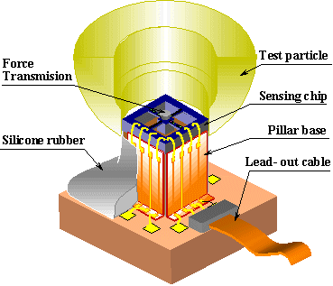
@The sensor configuration is shown in Fig. 1. The sensing chip is a crossbeam with piezoresistors on the upper surface. The test particle has a diameter of 8mm and is made of polyethylene. Its centroid will coincide with the center of the surface of the crossbeam to minimize the moment induced by horizontal force components. Forces and/or moments acting on the test particle will be transmitted to the sensing chip via a force transmission pillar placed at the center of the sensing chip.
@The model of sensing chip was analyzed by FEM to investigate the stress field in the structure, and to refine the specifications of the beam dimensions. The final dimensions of each arm of the crossbeam are 500 x 120 x 40Êm3.
@The
principal axes of piezoresistors are aligned with the crystal
directions ![]() and
and
![]() of silicon
(111). Based on the stress distribution in the sensing chip,
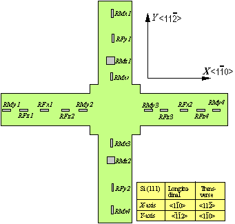
16 identical p-type conventional piezoresistors, (including 4-RFz , 2-RFx , 2-RFy , 4-RMx , and 4-RMy to detect Fz, Fx,
Fy, Mx, and My, respectively), and 2
identical p-type four-terminal piezoresistors (RMz1 ,RMz2
to measure Mz), are arranged on the
centerlines of the upper surface of an n-type silicon crossbeam,
(Fig. 2).
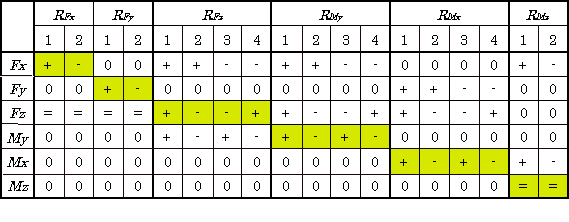
Table 1
summarizes the increases and decreases of resistance for the
normal piezoresistors and output voltage of the four-terminal
piezoresistors due to the applied loads; e+f and e-f
indicate respectively an increase and decrease, 0 means unchanged
and e=f means a similar change in both sign and magnitude in
the piezoresistors of a corresponding bridge.
of silicon
(111). Based on the stress distribution in the sensing chip,
16 identical p-type conventional piezoresistors, (including 4-RFz , 2-RFx , 2-RFy , 4-RMx , and 4-RMy to detect Fz, Fx,
Fy, Mx, and My, respectively), and 2
identical p-type four-terminal piezoresistors (RMz1 ,RMz2
to measure Mz), are arranged on the
centerlines of the upper surface of an n-type silicon crossbeam,
(Fig. 2).
Table 1
summarizes the increases and decreases of resistance for the
normal piezoresistors and output voltage of the four-terminal
piezoresistors due to the applied loads; e+f and e-f
indicate respectively an increase and decrease, 0 means unchanged
and e=f means a similar change in both sign and magnitude in
the piezoresistors of a corresponding bridge.
@The output characteristics and the sensitivity have been thoroughly analyzed. In response to the i th component, Li, of force or moment, the output voltageV iout is given by
V iout =S i Li =S ig S ist S ic Li , where S ig ,S ist ,S ic are stress, structural and circuit sensitivity for that component.
@Total number of piezoresistors is fewer than that of the prior art piezoresistive-based 6-DOF micro force sensors known to the authors.

Figure 1. Configuratin of sensor.
@

Figure 2. Arrangement of piezoresistors.
@
Table1. Increases and decreases of resistance of normal piezoresistors and output voltage of shear piezoresistors.

@
@
@